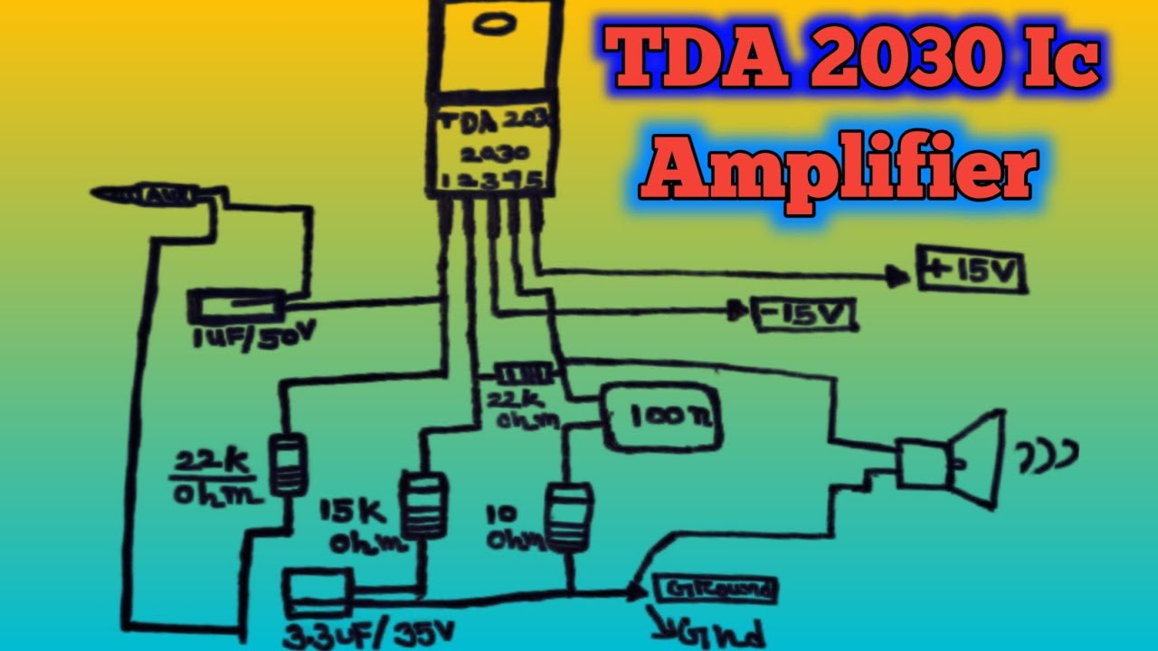
Tda2030 Amplifier Circuit Diagram. Tda2030 bridge amplifier circuit diagram with pcb layout, output of 35w at 8 ohms. in this article, we will explore the specifications of the tda2030 ic, discuss the circuit diagram of the amplifier with passive tone control, and highlight the key features and benefits of this minimalist design. Or other useful amplifier circuit diagrams are quite abundant in internet as tda2030 was used to very popular audio ic chip for amplifier diy before. build your own tda2030 ic amplifier circuit with this simple tutorial from electroschematics. Practically operational amplifier schematics can be found in the technical document of stmicroelectronics. in this article, we will explore tda2030 amplifier circuit diagram with tone control using 4558 ic, discuss working principle of the amplifier circuit, and its benefits. this circuit diagram provides all of the information needed to create a robust amp that can output up to 30w of power. 14w rms into 4ω at 0.5% thd, 12w rms into 8ω at 0.5% thd; Tda2030 amplifier circuit 12v, it is possible to operate the tda2030 amplifier circuit in 12 volts, but we should follow the instruction to building.
from www.youtube.com
in this article, we will explore tda2030 amplifier circuit diagram with tone control using 4558 ic, discuss working principle of the amplifier circuit, and its benefits. Or other useful amplifier circuit diagrams are quite abundant in internet as tda2030 was used to very popular audio ic chip for amplifier diy before. 14w rms into 4ω at 0.5% thd, 12w rms into 8ω at 0.5% thd; Tda2030 amplifier circuit 12v, it is possible to operate the tda2030 amplifier circuit in 12 volts, but we should follow the instruction to building. in this article, we will explore the specifications of the tda2030 ic, discuss the circuit diagram of the amplifier with passive tone control, and highlight the key features and benefits of this minimalist design. Practically operational amplifier schematics can be found in the technical document of stmicroelectronics. build your own tda2030 ic amplifier circuit with this simple tutorial from electroschematics. this circuit diagram provides all of the information needed to create a robust amp that can output up to 30w of power. Tda2030 bridge amplifier circuit diagram with pcb layout, output of 35w at 8 ohms.
tda2030 Audio Amplifier tda2030 ic 5.1 amplifier tda2030 ic check
Tda2030 Amplifier Circuit Diagram 14w rms into 4ω at 0.5% thd, 12w rms into 8ω at 0.5% thd; Practically operational amplifier schematics can be found in the technical document of stmicroelectronics. in this article, we will explore the specifications of the tda2030 ic, discuss the circuit diagram of the amplifier with passive tone control, and highlight the key features and benefits of this minimalist design. Tda2030 bridge amplifier circuit diagram with pcb layout, output of 35w at 8 ohms. this circuit diagram provides all of the information needed to create a robust amp that can output up to 30w of power. Or other useful amplifier circuit diagrams are quite abundant in internet as tda2030 was used to very popular audio ic chip for amplifier diy before. in this article, we will explore tda2030 amplifier circuit diagram with tone control using 4558 ic, discuss working principle of the amplifier circuit, and its benefits. Tda2030 amplifier circuit 12v, it is possible to operate the tda2030 amplifier circuit in 12 volts, but we should follow the instruction to building. 14w rms into 4ω at 0.5% thd, 12w rms into 8ω at 0.5% thd; build your own tda2030 ic amplifier circuit with this simple tutorial from electroschematics.